Going to back to basics (from this post), since I wasn’t able to go straight to getting my display working with the ESP32 and LVGL. This post documents the steps and pinout to integrate the ESP32 Devkitv1 (30-pin version) with the 3.5″Adafruit Display.
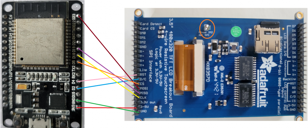
First up, the schematic:
Note that the IM2 pads (orange circle) are soldered together for SPI mode.

| ESP32 | Display |
| 3v3 | 3-5v |
| GND | GND |
| D2 | D/C |
| D4 | RST |
| D5 | CS |
| D18 | CLK |
| D19 | MISO |
| D23 | MOSI |
A few points of confusion that I personally ran into were mapping the esp32 pins to the schematic, silk screen on the esp32 itself and the pinouts found online. You can see in the code below that the Dx number matches the pin #defines from the code.
Second, the simplified code:
#include "Adafruit_HX8357.h"

// TFT display and SD card will share the hardware SPI interface.
// Hardware SPI pins are specific to the Arduino board type and
// cannot be remapped to alternate pins.  For Arduino Uno,
// Duemilanove, etc., pin 11 = MOSI, pin 12 = MISO, pin 13 = SCK.

#define TFT_DC 2
#define TFT_CS 5
// Use hardware SPI (on Uno, #13, #12, #11) and the above for CS/DC
Adafruit_HX8357 tft = Adafruit_HX8357(TFT_CS, TFT_DC);

void setup(void)
{
  tft.begin();
  tft.fillScreen(HX8357_RED);
}

void loop()
{

}
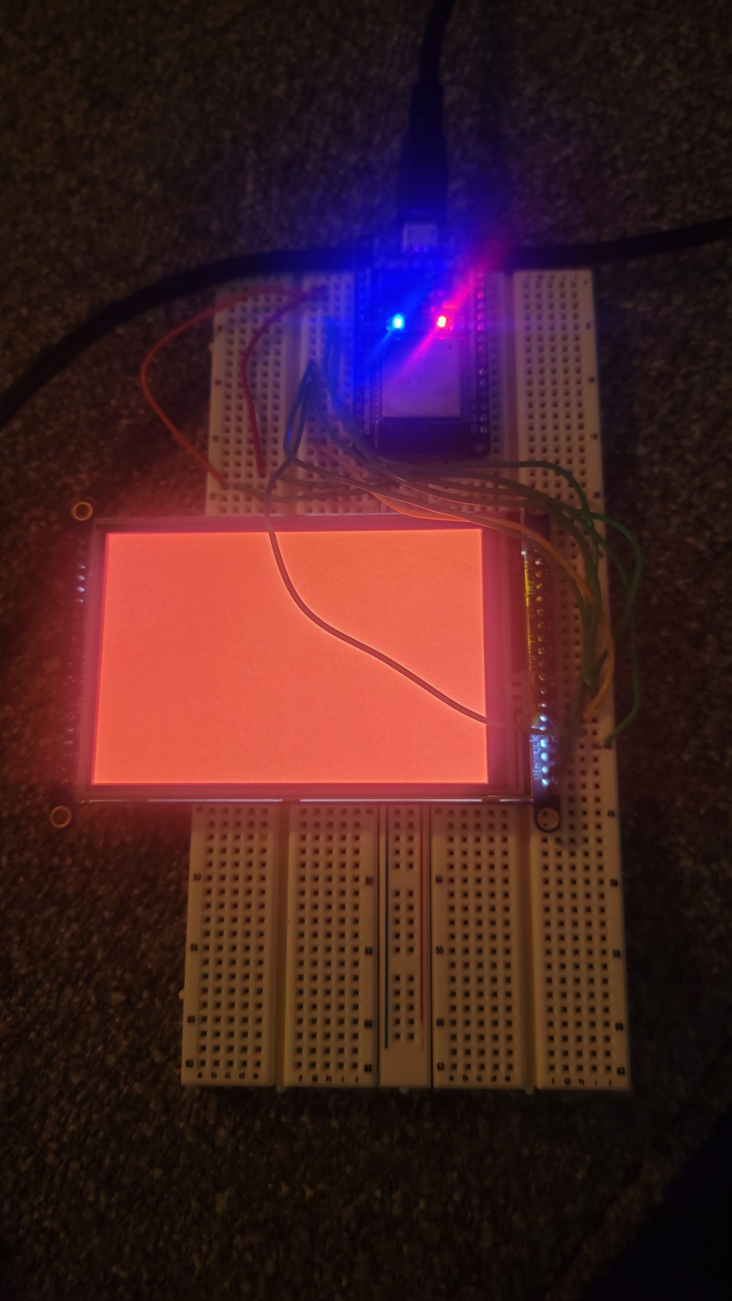
And the final, somewhat anticlimactic, outcome:


