Process documenting my attempts at getting the LVGL libraries working with my ESP32 Devkitv1 and Adafruit 3.5″ touchscreen display.
So far I’ve found a these articles that seemed useful:
– https://randomnerdtutorials.com/lvgl-cheap-yellow-display-esp32-2432s028r/
– https://randomnerdtutorials.com/lvgl-esp32-tft-touchscreen-display-ili9341-arduino/
Through the links above it was the first time I’ve heard about Squareline. That program seems very useful and has a large userbase. Its similar to Nextion in what it can draw but may be more powerful.
Day 1:
Focusing on getting the ESP32 connected to the display and capable on controlling it, this tutorial seems the most useful: https://randomnerdtutorials.com/lvgl-esp32-tft-touchscreen-display-ili9341-arduino/.
Following that tutorial I selected Tools > Board and select ESP32 > ESP32 Dev Module to enable the ESP32 Devkit v1 which happened to be on COM11.
Compilation completed successfully but when trying to program I received this error:Sketch uses 517361 bytes (39%) of program storage space. Maximum is 1310720 bytes.
Global variables use 48992 bytes (14%) of dynamic memory, leaving 278688 bytes for local variables. Maximum is 327680 bytes.
esptool.py v4.6
Serial port COM11
Connecting....
Chip is ESP32-D0WDQ6 (revision v1.0)
Features: WiFi, BT, Dual Core, 240MHz, VRef calibration in efuse, Coding Scheme None
Crystal is 40MHz
MAC: 10:52:1c:67:97:0c
Uploading stub...
Running stub...
Stub running...
Changing baud rate to 921600
Changed.
WARNING: Failed to communicate with the flash chip, read/write operations will fail. Try checking the chip connections or removing any other hardware connected to IOs.
Configuring flash size...
Traceback (most recent call last):
File "esptool.py", line 37, in <module>
File "esptool\__init__.py", line 1064, in _main
File "esptool\__init__.py", line 859, in main
File "esptool\cmds.py", line 466, in write_flash
File "esptool\util.py", line 37, in flash_size_bytes
TypeError: argument of type 'NoneType' is not iterable
[20500] Failed to execute script 'esptool' due to unhandled exception!
Failed uploading: uploading error: exit status 1
After a fair bit of debugging and googling I finally removed it from the breadboard and it was able to program OK. I suspect one of the connected pins is also tied to the required boot/en pins.
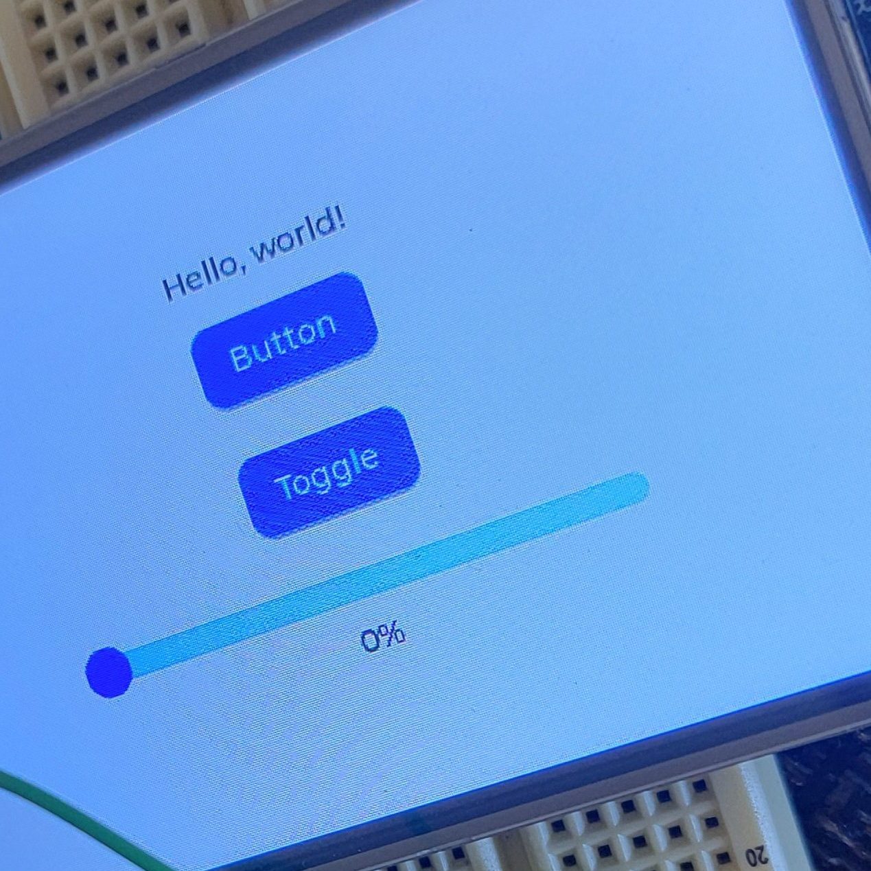
Powered it up after replacing the ESP32 on the breadboard and got this after it booted

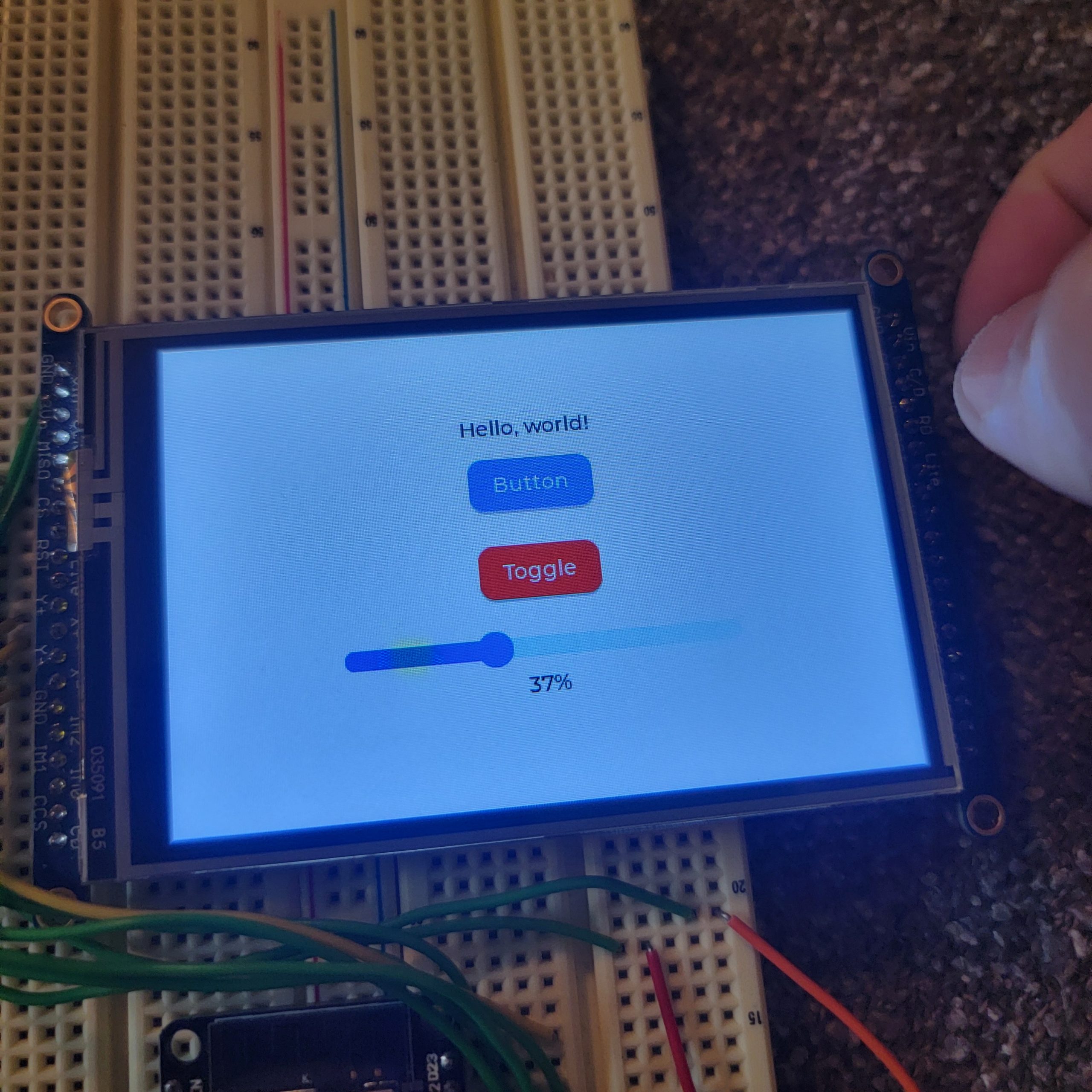
The above image it what it should resemble

Day 2:
Searching through the configuration file for potential differences I found the color depth in lv_conf and increased it from 16 to 32, which looked different but still not correct:

I decided to disable to touchscreen inputs because the default chip used in the tutorial was not the one I had on my LCD:
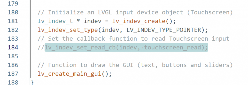
Also decided to try to play with the screen rotation setting it from 3 to 1:

Day 3
Still no luck so I’ve decided to simplify things and try to get one of the base examples from Adafruit working on the ESP32 Devkitv1 (as opposed to the UnoR3). This side quest will be tracked on a new post here.
Day 4
Returning from the side quest, after verifying the correct pinout I restarted from a fresh project. Again following the Adafruit tutorial but not using the predefine headers provided. They are for a display with the ili9341 drivers as opposed to my display which has a hx3857 driver and the customization doesn’t seem overly difficult since I verified the pinout during the Day 3 side quest.
Trimming code
The code from Adafruit used a touchscreen as well but for my needs and this test I felt it best to remove as much of that code as I could to narrow in on just getting the display up. Removing #defines and unused touchscreen objects/initialization I started from this code in my sketch file:
/*  Rui Santos & Sara Santos - Random Nerd Tutorials
    THIS EXAMPLE WAS TESTED WITH THE FOLLOWING HARDWARE:
    1) ESP32-2432S028R 2.8 inch 240×320 also known as the Cheap Yellow Display (CYD): https://makeradvisor.com/tools/cyd-cheap-yellow-display-esp32-2432s028r/
      SET UP INSTRUCTIONS: https://RandomNerdTutorials.com/cyd-lvgl/
    2) REGULAR ESP32 Dev Board + 2.8 inch 240x320 TFT Display: https://makeradvisor.com/tools/2-8-inch-ili9341-tft-240x320/ and https://makeradvisor.com/tools/esp32-dev-board-wi-fi-bluetooth/
      SET UP INSTRUCTIONS: https://RandomNerdTutorials.com/esp32-tft-lvgl/
    Permission is hereby granted, free of charge, to any person obtaining a copy of this software and associated documentation files.
    The above copyright notice and this permission notice shall be included in all copies or substantial portions of the Software.
*/

/*  Install the "lvgl" library version 9.X by kisvegabor to interface with the TFT Display - https://lvgl.io/
    *** IMPORTANT: lv_conf.h available on the internet will probably NOT work with the examples available at Random Nerd Tutorials ***
    *** YOU MUST USE THE lv_conf.h FILE PROVIDED IN THE LINK BELOW IN ORDER TO USE THE EXAMPLES FROM RANDOM NERD TUTORIALS ***
    FULL INSTRUCTIONS AVAILABLE ON HOW CONFIGURE THE LIBRARY: https://RandomNerdTutorials.com/cyd-lvgl/ or https://RandomNerdTutorials.com/esp32-tft-lvgl/   */
#include <lvgl.h>

/*  Install the "TFT_eSPI" library by Bodmer to interface with the TFT Display - https://github.com/Bodmer/TFT_eSPI
    *** IMPORTANT: User_Setup.h available on the internet will probably NOT work with the examples available at Random Nerd Tutorials ***
    *** YOU MUST USE THE User_Setup.h FILE PROVIDED IN THE LINK BELOW IN ORDER TO USE THE EXAMPLES FROM RANDOM NERD TUTORIALS ***
    FULL INSTRUCTIONS AVAILABLE ON HOW CONFIGURE THE LIBRARY: https://RandomNerdTutorials.com/cyd-lvgl/ or https://RandomNerdTutorials.com/esp32-tft-lvgl/   */
#include <TFT_eSPI.h>

#define SCREEN_WIDTH 480
#define SCREEN_HEIGHT 320

// Touchscreen coordinates: (x, y) and pressure (z)
int x, y, z;

#define DRAW_BUF_SIZE ((SCREEN_WIDTH * SCREEN_HEIGHT) / 10 * (LV_COLOR_DEPTH / 8))
uint32_t draw_buf[DRAW_BUF_SIZE / 4];

// If logging is enabled, it will inform the user about what is happening in the library
void log_print(lv_log_level_t level, const char * buf) {
  LV_UNUSED(level);
  Serial.println(buf);
  Serial.flush();
}

// Get the Touchscreen data
void touchscreen_read(lv_indev_t * indev, lv_indev_data_t * data) {
  // Checks if Touchscreen was touched, and prints X, Y and Pressure (Z)
  data->state = LV_INDEV_STATE_RELEASED;
}

int btn1_count = 0;
// Callback that is triggered when btn1 is clicked
static void event_handler_btn1(lv_event_t * e) {
  lv_event_code_t code = lv_event_get_code(e);
  if(code == LV_EVENT_CLICKED) {
    btn1_count++;
    LV_LOG_USER("Button clicked %d", (int)btn1_count);
  }
}

// Callback that is triggered when btn2 is clicked/toggled
static void event_handler_btn2(lv_event_t * e) {
  lv_event_code_t code = lv_event_get_code(e);
  lv_obj_t * obj = (lv_obj_t*) lv_event_get_target(e);
  if(code == LV_EVENT_VALUE_CHANGED) {
    LV_UNUSED(obj);
    LV_LOG_USER("Toggled %s", lv_obj_has_state(obj, LV_STATE_CHECKED) ? "on" : "off");
  }
}

static lv_obj_t * slider_label;
// Callback that prints the current slider value on the TFT display and Serial Monitor for debugging purposes
static void slider_event_callback(lv_event_t * e) {
  lv_obj_t * slider = (lv_obj_t*) lv_event_get_target(e);
  char buf[8];
  lv_snprintf(buf, sizeof(buf), "%d%%", (int)lv_slider_get_value(slider));
  lv_label_set_text(slider_label, buf);
  lv_obj_align_to(slider_label, slider, LV_ALIGN_OUT_BOTTOM_MID, 0, 10);
  LV_LOG_USER("Slider changed to %d%%", (int)lv_slider_get_value(slider));
}

void lv_create_main_gui(void) {
  // Create a text label aligned center on top ("Hello, world!")
  lv_obj_t * text_label = lv_label_create(lv_screen_active());
  lv_label_set_long_mode(text_label, LV_LABEL_LONG_WRAP);    // Breaks the long lines
  lv_label_set_text(text_label, "Hello, world!");
  lv_obj_set_width(text_label, 150);    // Set smaller width to make the lines wrap
  lv_obj_set_style_text_align(text_label, LV_TEXT_ALIGN_CENTER, 0);
  lv_obj_align(text_label, LV_ALIGN_CENTER, 0, -90);

  lv_obj_t * btn_label;
  // Create a Button (btn1)
  lv_obj_t * btn1 = lv_button_create(lv_screen_active());
  lv_obj_add_event_cb(btn1, event_handler_btn1, LV_EVENT_ALL, NULL);
  lv_obj_align(btn1, LV_ALIGN_CENTER, 0, -50);
  lv_obj_remove_flag(btn1, LV_OBJ_FLAG_PRESS_LOCK);

  btn_label = lv_label_create(btn1);
  lv_label_set_text(btn_label, "Button");
  lv_obj_center(btn_label);

  // Create a Toggle button (btn2)
  lv_obj_t * btn2 = lv_button_create(lv_screen_active());
  lv_obj_add_event_cb(btn2, event_handler_btn2, LV_EVENT_ALL, NULL);
  lv_obj_align(btn2, LV_ALIGN_CENTER, 0, 10);
  lv_obj_add_flag(btn2, LV_OBJ_FLAG_CHECKABLE);
  lv_obj_set_height(btn2, LV_SIZE_CONTENT);

  btn_label = lv_label_create(btn2);
  lv_label_set_text(btn_label, "Toggle");
  lv_obj_center(btn_label);

  // Create a slider aligned in the center bottom of the TFT display
  lv_obj_t * slider = lv_slider_create(lv_screen_active());
  lv_obj_align(slider, LV_ALIGN_CENTER, 0, 60);
  lv_obj_add_event_cb(slider, slider_event_callback, LV_EVENT_VALUE_CHANGED, NULL);
  lv_slider_set_range(slider, 0, 100);
  lv_obj_set_style_anim_duration(slider, 2000, 0);

  // Create a label below the slider to display the current slider value
  slider_label = lv_label_create(lv_screen_active());
  lv_label_set_text(slider_label, "0%");
  lv_obj_align_to(slider_label, slider, LV_ALIGN_OUT_BOTTOM_MID, 0, 10);
}

void setup() {
  String LVGL_Arduino = String("LVGL Library Version: ") + lv_version_major() + "." + lv_version_minor() + "." + lv_version_patch();
  Serial.begin(115200);
  Serial.println(LVGL_Arduino);

  // Start LVGL
  lv_init();
  // Register print function for debugging
  lv_log_register_print_cb(log_print);

  // Create a display object
  lv_display_t * disp;
  // Initialize the TFT display using the TFT_eSPI library
  disp = lv_tft_espi_create(SCREEN_WIDTH, SCREEN_HEIGHT, draw_buf, sizeof(draw_buf));

  // Initialize an LVGL input device object (Touchscreen)
  lv_indev_t * indev = lv_indev_create();
  lv_indev_set_type(indev, LV_INDEV_TYPE_POINTER);
  // Set the callback function to read Touchscreen input
  lv_indev_set_read_cb(indev, touchscreen_read);

  // Function to draw the GUI (text, buttons and sliders)
  lv_create_main_gui();
}

void loop()
{
  lv_task_handler();  // let the GUI do its work
  lv_tick_inc(5);     // tell LVGL how much time has passed
  delay(5);           // let this time pass
}
Controller definition
Modified TFT_eSPI/User_Setup.h to select the correct controller:
// Only define one driver, the other ones must be commented out
//#define ILI9341_DRIVER       // Generic driver for common displays
//#define ILI9341_2_DRIVER     // Alternative ILI9341 driver, see https://github.com/Bodmer/TFT_eSPI/issues/1172
//#define ST7735_DRIVER      // Define additional parameters below for this display
//#define ILI9163_DRIVER     // Define additional parameters below for this display
//#define S6D02A1_DRIVER
//#define RPI_ILI9486_DRIVER // 20MHz maximum SPI
#define HX8357D_DRIVER
//#define ILI9481_DRIVER
//#define ILI9486_DRIVER
//#define ILI9488_DRIVER     // WARNING: Do not connect ILI9488 display SDO to MISO if other devices share the SPI bus (TFT SDO does NOT tristate when CS is high)
//#define ST7789_DRIVER      // Full configuration option, define additional parameters below for this display
//#define ST7789_2_DRIVER    // Minimal configuration option, define additional parameters below for this display
//#define R61581_DRIVER
//#define RM68140_DRIVER
//#define ST7796_DRIVER
//#define SSD1351_DRIVER
//#define SSD1963_480_DRIVER
//#define SSD1963_800_DRIVER
//#define SSD1963_800ALT_DRIVER
//#define ILI9225_DRIVER
//#define GC9A01_DRIVER
Pinout updates
Again, leveraging what I discovered in Day 3’s side quest, I purposely left the others commented out because they were not defined. I updated the pinout in TFT_eSPI/User_Setup.h as shown in the excerpt below:
// ###### EDIT THE PIN NUMBERS IN THE LINES FOLLOWING TO SUIT YOUR ESP32 SETUP   ######

// For ESP32 Dev board (only tested with ILI9341 display)
// The hardware SPI can be mapped to any pins

//#define TFT_MISO 19
//#define TFT_MOSI 23
//#define TFT_SCLK 18
#define TFT_CS    5  // Chip select control pin
#define TFT_DC    2  // Data Command control pin
//#define TFT_RST   4  // Reset pin (could connect to RST pin)
//#define TFT_RST  -1  // Set TFT_RST to -1 if display RESET is connected to ESP32 board RST
Incorrect SCLK frequency
I began looking on message boards for potential errors others ran in to, eventually coming across this post. The original poster discovered an error in the code which didn’t allow the SPI clock (SCLK) frequency to be increased, but more importantly, mentioned 16MHz as the desired frequency for the controller. Recalling that I saw a frequency of 40MHz in the TFT_eSPI/User_Setup.h file I went back and tried setting these to 16MHz as shown in the excerpt below:
// #define SPI_FREQUENCY   1000000
// #define SPI_FREQUENCY   5000000
#define SPI_FREQUENCY  16000000
// #define SPI_FREQUENCY  20000000
//#define SPI_FREQUENCY  27000000
// #define SPI_FREQUENCY  40000000
// #define SPI_FREQUENCY  55000000 // STM32 SPI1 only (SPI2 maximum is 27MHz)
// #define SPI_FREQUENCY  80000000

// Optional reduced SPI frequency for reading TFT
#define SPI_READ_FREQUENCY  16000000
When this was set incorrectly the display looked like:

Incorrect color depth
Incorrectly I had changed the color depth to 32 in other attempts but I discovered the correct setting is 16:
/*====================
   COLOR SETTINGS
 *====================*/

/*Color depth: 8 (A8), 16 (RGB565), 24 (RGB888), 32 (XRGB8888)*/
#define LV_COLOR_DEPTH 16
When this was set incorrectly the screen displayed:
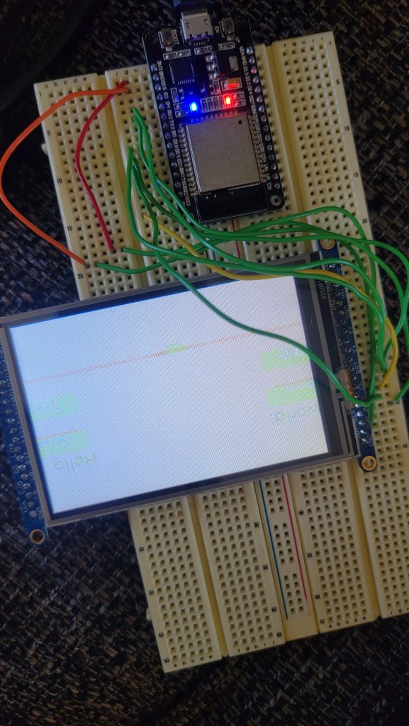
Final outcome with the correct settings
Once all the above issues were corrected the display behaved and looked as expected, matching the Adafruit outcome:
